Lập trình C cho hệ thống nhúng (P6- AD Converter trong V850E)
Bài đăng này đã không được cập nhật trong 4 năm
1. AD Converter là gì
Định nghĩa :
Trong các ứng dụng đo lường và điều khiển bằng vi điều khiển bộ chuyển đổi tương tự-số (ADC) là một thành phần rất quan trọng. Dữ liệu trong thế giới của chúng ta là các dữ liệu tương tự (analog). Ví dụ nhiệt độ không khí buổi sáng là 25oC và buổi trưa là 32oC, giữa hai mức giá trị này có vô số các giá trị liên tục mà nhiệt độ phải “đi qua” để có thể đạt mức 32oC từ 25oC, đại lượng nhiệt độ như thế gọi là một đại lượng analog. Trong khi đó, rõ ràng vi điều khiển là một thiết bị số (digital), các giá trị mà một vi điều khiển có thể thao tác là các con số rời rạc vì thực chất chúng được tạo thành từ sự kết hợp của hai mức 0 và 1. Ví dụ chúng ta muốn dùng một thanh ghi 8 bit trong vi điều khiển để lưu lại các giá trị nhiệt độ từ 0oC đến 255 oC, như chúng ta đã biết, một thanh ghi 8 bit có thể chứa tối đa 256 (28) giá trị nguyên từ 0 đến 255, như thế các mức nhiệt độ không nguyên như 28.123 oC sẽ không được ghi lại. Nói cách khác, chúng ta đã “số hóa” (digitalize) một dữ liệu analog thành một dữ liệu digital. Quá trình “số hóa” này thường được thực hiện bởi một thiết bị gọi là “bộ chuyển đổi tương tự - số hay đơn giản là ADC (Analog to Digital Converter).
Độ phân giải của AD converter :
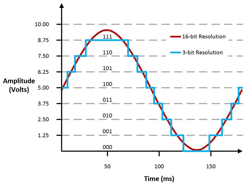
Khái niệm độ phân giải được dùng để chỉ số bit cần thiết để chứa hết các mức giá trị digital ngõ ra. Trong trường hợp có 8 mức giá trị ngõ ra, chúng ta cần 3 bit nhị phân để mã hóa hết các giá trị này, vì thế mạch chuyển đổi ADC với 7 bộ so sánh sẽ có độ phân giải là 3 bit. Một cách tổng quát, nếu một mạch chuyển đổi ADC có độ phân giải n bit thì sẽ có 2n mức giá trị có thể có ở ngõ ra digital. Để tạo ra một mạch chuyển đổi flash ADC có độ phân giải n bit, chúng ta cần đến 2n-1 bộ so sánh, giá trị này rất lớn khi thiết kế bộ chuyển đổi ADC có độ phân giải cao, vì thế các bộ chuyển đổi flash ADC thường có độ phân giải ít hơn 8 bit. Độ phân giải liên quan mật thiết đến chất lượng chuyển đổi ADC, việc lựa chọn độ phân giải phải phù hợp với độ chính xác yêu cầu và khả năng xử lý của bô điều khiển.
Ví dụ về độ phân giải trong việc “số hóa” một hàm sin analog thành dạng digital.
2. Sử dụng AD Converter trong V850
Bây giờ chúng ta sẽ sử dụng AD Converter trong V850 qua đoạn chương trình dưới đây.
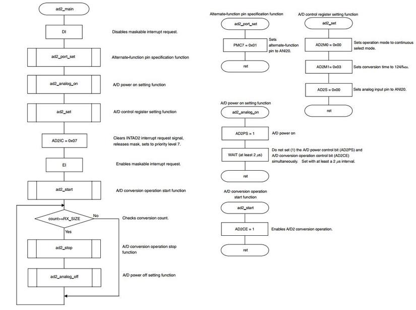
Mô tả chương trình Function] Performs A/D conversion by setting the A/D conversion operation start timing to continuous select mode of software trigger mode. [Function name] ad2main [Processing content] Starts A/D conversion by setting the AD2M0.AD2CE bit to 1. Stores the A/D conversion result to buf[] by A/D converting the ANI20 pin input. An A/D2 conversion end interrupt request signal (INTAD2) occurs upon completion of every A/D conversion. After A/D conversion, the conversion is performed repeatedly unless the AD2CE bit is set to 0. Performs A/D conversion for 10 times. [SFR used] AD2IC: 0x07 (Clears A/D2 conversion end interrupt request signal (INTAD2), releases mask, sets to priority level 7.) [call function] ad2portset, ad2analogon, ad2set, ad2start, ad2stop, ad2analogoff [Variables] unsigned short int buf [ ]: Conversion data storing buffer volatile unsigned char count: Conversion count variable unsigned char wait: WAIT variable [Interrupt] ad2int [Interrupt source] INTAD2*
Sơ đồ khối cho toàn bộ các function
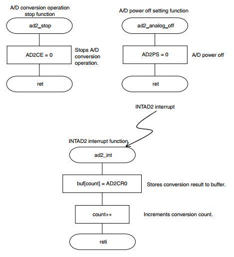
Implement code cho các function trên
/*───────────────────────────────────
*   Function Prototypes
* ───────────────────────────────────
*/
void ad2_main(void);					/* AD2 function */
void ad2_port_set(void);				/* Alternate-function pin setting function */
void ad2_set(void);						/* A/D converter 2 control register setting function */
void ad2_analog_on(void);				/* Analog power supply ON setting function */
void ad2_start(void);					/* A/D conversion operation start function */
void ad2_stop(void);					/* A/D conversion operation stop function */
void ad2_analog_off(void);				/* Analog power supply OFF setting function */
/*───────────────────────────────────
*   Global Variable
* ───────────────────────────────────
*/
#define	RX_SIZE	10						/* Conversion data buffer size */
unsigned short int  buf[RX_SIZE];		/* Conversion data store buffer */
volatile unsigned char count;			/* A/D conversion count variable */
unsigned char wait;						/* WAIT variable */
/*───────────────────────────────────
*  Ad2_Main Function
* ───────────────────────────────────
*/
void ad2_main(void)
{
	__DI();								/* Maskable interrupt disabled */

	ad2_port_set();						/* Alternate-function pin setting function */

	ad2_analog_on();					/* Analog power supply ON setting function */

	ad2_set();							/* A/D converter 2 control register setting function */

	AD2IC = 0x07;						/* INTAD2 interrupt request signal clear, mask release, priority level 7 set */
	__EI();								/* Maskable interrupt enabled */

	ad2_start();						/* A/D conversion operation start function */

	while(1){
		if(count>=RX_SIZE){				/* Conversion count judgment */
			ad2_stop();					/* A/D conversion operation stop function */
			ad2_analog_off();			/* Analog power supply OFF setting function */
		}
	}

}

/*───────────────────────────────────
*   Ad2_Port_Set Function
* ───────────────────────────────────
*/
void ad2_port_set(void)
{

	/* Set alternative-function pin to ANI20. */
	PMC7 |= 0x01;						/* bit 0: Input port/ANI20 input pin specification */

	return;
}

/*───────────────────────────────────
*   Ad2_Analog_On Function
* ───────────────────────────────────
*/
void ad2_analog_on(void)
{
	/* Analog power supply ON */
	AD2M0 |= 0x40;
	/*AD2PS = 1;*/						/* 1: Analog power supply ON, 0: Analog power supply OFF */

	for(wait=0; wait<=28; wait++); 		/* Set the AD2CE bit at least 2 us after the AD2PS bit was set. */
										/* This wait is about 5.1 us. */

	return;
}

/*───────────────────────────────────
*   Ad2_Set Function
* ───────────────────────────────────
*/
void ad2_set(void)
{
	/* Register for specifying A/D conversion buffer mode and operation mode */
	/* 1-buffer mode, continuous select mode */
	AD2M0 = 0x00;						/* bit 7: Conversion operation control */
										/* 1: Enable operation, 0: Stop operation */
										/* bit 6: Power supply control */
										/* 1: Power supply ON, 0: Power supply OFF */
										/* bit 5, bit 4: Operation mode specification */
										/* 00: Continuous select mode */
										/* 01: Continuous scan mode */
										/* 10: One-shot select mode */
										/* 11: One-shot scan mode */

	/* Register for specifying sampling clock for analog input and resolution */
	/* fxx/16 (4 MHz), 10 bits (2048 times) */
	AD2M1 = 0x03;						/* bit 3, bit 2, bit 1, bit 0: Sampling clock specification */

	/* Analog input pin specification register */
	/* ANI20 */
	AD2S = 0x00;					/* bit 2, bit 1, bit 0: Analog input pin specification */

	return;
}

/*───────────────────────────────────
*   Ad2_Start Function
* ───────────────────────────────────
*/
void ad2_start(void)
{
	/* Start conversion operation */
	AD2CE = 1;							/* 1: Start conversion operation, 0: Stop conversion operation */

	return;
}

/*───────────────────────────────────
*   Ad2_Stop Function
* ───────────────────────────────────
*/
void ad2_stop(void)
{
	/* Stop conversion operation */
	AD2CE = 0;							/* 1: Start conversion operation, 0: Stop conversion operation */

	return;
}

/*───────────────────────────────────
*   Ad2_Analog_Off Function
* ───────────────────────────────────
*/
void ad2_analog_off(void)
{
	/* Analog power supply OFF */
	AD2M0 &= 0xB1;
/*	AD2PS = 0;		*/					/* 1: Analog power supply ON, 0: Analog power supply OFF */

	return;
}

/*───────────────────────────────────
*   Interrupt Function
* ───────────────────────────────────
*/
__interrupt
void ad2_int(void)
{
	buf[count] = AD2CR0;				/* Store conversion result */
	count++;							/* Variable count increment */
}
All rights reserved